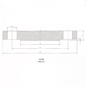
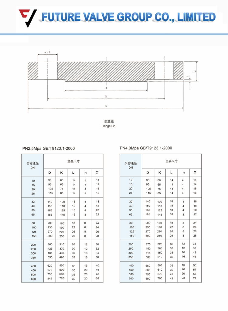
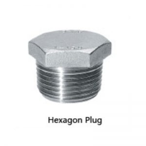
PN25 PN40 blind flange lid
size:DN10~DN600 (1/4″~24″)
material:Q235,A105N,F304,F304L,F316,F316L,F321,etc.
描述
FLANGE BASICS: FUNCTIONS, DESIGNS, AND OTHER CONSIDERATIONS
A look at the common characteristics you should consider when choosing a flange for your piping system
WHAT ARE PIPE FLANGES AND HOW DO THEY WORK?
Offering a reliable way to connect pipe systems with the various equipment, valves, and other components of virtually any processing system, flanges are the second most used joining method after welding.
Using flanges adds flexibility when maintaining piping systems by allowing for easier disassembly and improved access to system components.
A typical flanged connection is comprised of three parts:
- Pipe Flanges
- Gasket
- Bolting
In most cases, there are specific gasket and bolting materials made from the same, or approved materials as the piping components you wish to connect. Stainless Steel flanges are some of the most common. However, flanges are available in a wide range of materials so matching them with your needs is essential.
Other common flange materials include Monel, Inconel, Chrome Moly, and many others depending on the application.
The best option for your needs will depend on both the system in which you intend to use the flange and your specific requirements.
COMMON FLANGE TYPES AND CHARACTERISTICS
Flanges are not a one-type-fits-all sort of solution. Sizing aside, matching the ideal flange design to your piping system and intended usage will help to ensure reliable operation, a long service life, and optimal pricing.
Here’s a look at the most common flange types available.
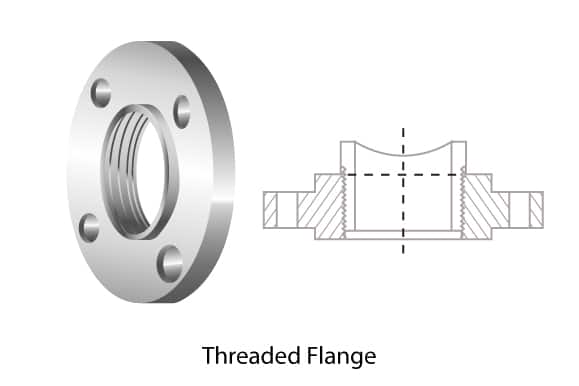
THREADED FLANGESAlso known as a screwed flange, this style has a thread inside the flange bore which fits with the matching male thread on the pipe or fitting. The threaded connection means you can avoid welding in many use cases. Simply match the threading to the pipes you wish to connect. |
 |
SOCKET-WELD FLANGESIdeal for smaller pipe diameters in low-temperature and low-pressure scenarios, socket-weld flanges feature a connection in which you place the pipe into the flange and then secure the connection with a single multi-pass fillet weld. This makes this style simpler to install than other welded flange types while avoiding the limitations associated with threaded ends. |
|
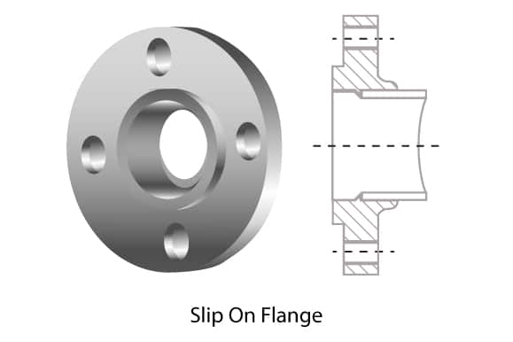
SLIP-ON FLANGESSlip-on flanges are very common and are available in a large range of sizes to accommodate systems with higher flow rates and throughput. Simply match the flange to the outer diameter of the pipe you intend to connect. Installation is slightly more technical as you’ll need fillet weld both sides to secure the flange to the pipe. |
 |
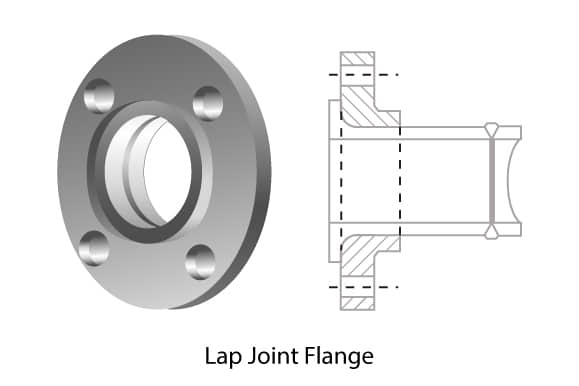
LAP JOINT FLANGESFeaturing a two-piece design, lap joint flanges require butt welding of the stub end to the pipe or fitting with the use of a backing flange to create the flanged connection. This design makes this style popular for use in systems with limited physical space or systems which require frequent dismantling and maintenance. |
 |
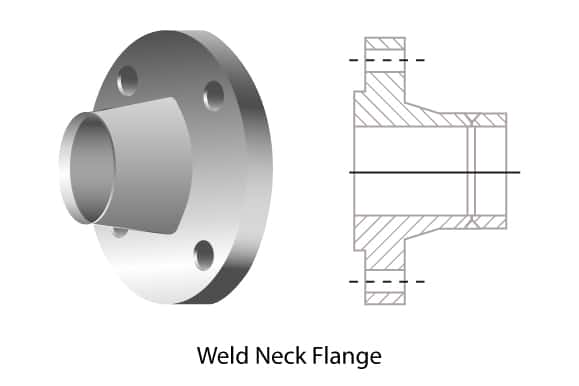
WELD NECK FLANGESLike lap joint flanges, weld neck flanges require butt welding for installation. However, their integrity, performance in systems with multiple repeat bends, and the ability to use them in high-pressure and high-temperature systems make them a leading choice for process piping. |
 |
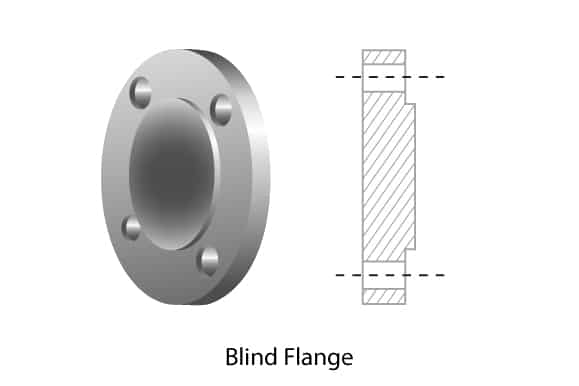
BLIND FLANGESUsed for terminating or isolating piping systems, blind flanges are essentially boltable blank discs. When installed properly and combined with the correct gaskets, they can achieve an outstanding seal which is easy to remove when needed. |
 |
SPECIALTY FLANGESThe flange types listed above are the most common. However, there is a range of additional specialized flange types available to suit a range of uses and environments. Other options include nipoflanges, weldoflanges, expanding flanges, orifice, long weld neck and reducing flanges. |
MAKING THE CONNECTION: FLANGE FACING TYPES
Flange design is only the start when considering the ideal flange for your piping system. Face types are another characteristic that will have a major impact on the final performance and service life of your flanges.
Facing types determine both the gaskets needed to install the flange and characteristics related to the seal created.
Common face types include:
- Flat Face (FF): As the name suggests, flat face flanges feature a flat, even surface combined with a full face gasket that contacts most of the flange surface.
- Raised Face (RF): These flanges feature a small raised section around the bore with an inside bore circle gasket.
- Ring Joint Face (RTJ): Used in high-pressure and high-temperature processes, this face type features a groove in which a metal gasket sits to maintain the seal.
- Tongue and Groove (T&G): These flanges feature matching grooves and raised sections. This aids in installation as the design helps the flanges to self-align and provides a reservoir for gasket adhesive.
- Male & Female (M&F): Similar to tongue and groove flanges, these flanges use a matching pair of grooves and raised sections to secure the gasket. However, unlike tongue and groove flanges, these retain the gasket on the female face, providing more accurate placement and increased gasket material options.
Many face types also offer one of two finishes: serrated or smooth.
Choosing between the options is important as they will determine the optimal gasket for a reliable seal.
In general, smooth faces work best with metallic gaskets while serrated faces help to create stronger seals with soft material gaskets.
THE PROPER FIT: A LOOK AT FLANGE DIMENSIONS
Apart from the functional design of a flange, flange dimensions are the most likely factor to impact flange choices when designing, maintaining, or updating a piping system.
However, you must consider how the flange interfaces with the pipe and the gaskets in use to ensure proper sizing.
Common considerations include:
- Outside diameter: The distance between two opposing edges of the flange face
- Thickness: A measure of the thickness of the outer attaching rim
- Bolt circle diameter: The distance between opposing bolt holes when measured from centre to centre
- Pipe size: A designation of the pipe size with which the flange corresponds
- Nominal bore size: A measurement of the flange connectors inner diameter
FLANGE CLASSIFICATION & SERVICE RATINGS
Each of the above characteristics will have an influence on how the flange performs across a range of processes and environments.
So how can you tell which flanges are up to the task and which are not?
Flanges are often classified based on their ability to withstand temperatures and pressures.
This is designated using a number and either the “#”, “lb”, or “class” suffix. These suffixes are interchangeable but will differ based on the region or vendor.
Common classifications include:
- 150#
- 300#
- 600#
- 900#
- 1500#
- 2500#
Exact pressure and temperature tolerances will vary by materials used, flange design, and flange size. The only constant is that in all cases, pressure ratings decrease as temperatures rise.
FLANGE STANDARDS AND MARKINGS
To help make comparison easier, flanges fall under global standards established by the American Society of Mechanical Engineers (ASME) — ASME B16.5 & B16.47.
If you’re attempting to replace or verify existing parts, all flanges must include markers — typically on their outer perimeter — to aid in the process.
These markers also follow a strict order:
- Manufacturer logo or code
- ASTM material code
- Material Grade
- Service rating (Pressure-temperature Class)
- Size
- Thickness (Schedule)
- Heat Number
- Special designations, if any — for example, QT for Quenched and tempered or W for repair by welding
This guide offers a solid foundation of the basics of flange design and how to choose the ideal flange for your piping system. However, with a wide range of stainless steel flanges and other flange materials available, it is impossible to list every configuration, detail, or consideration.

